
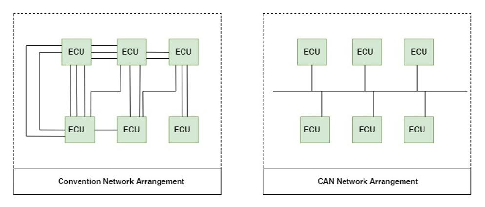
CAN-Bus is a protocol that enables message-based communication between systems, devices, and control units over a network. Thanks to the CAN-Bus communication protocol, communication between devices is achieved using twisted pair cables, eliminating the need for cable systems stretching for kilometers. By using the CAN-Bus protocol, the total wiring length in a vehicle has been reduced by approximately 1.5 kilometers, resulting in a weight saving of about 50 kilograms. This reduction has led to lifetime fuel savings in the vehicle.
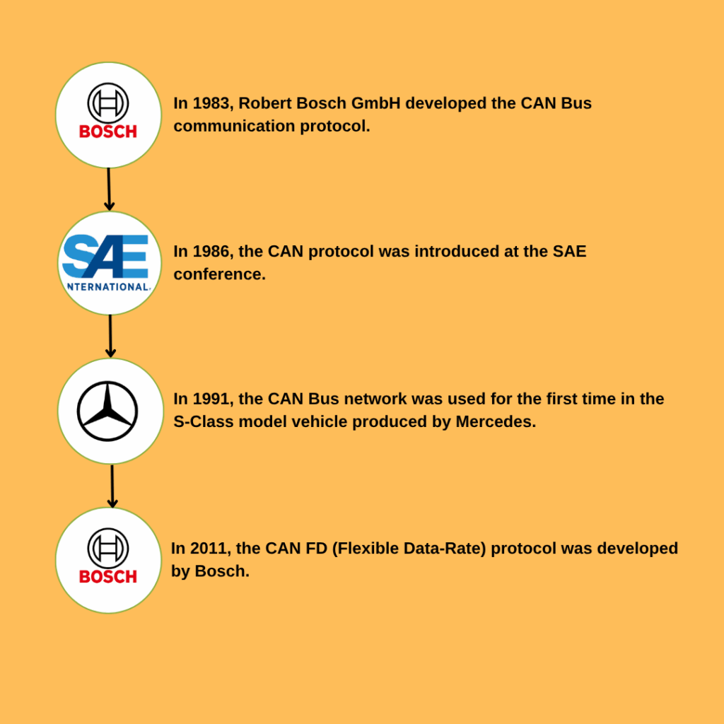
Work on the CAN Bus started in 1983 by Robert Bosch GmbH.
The CAN protocol was first introduced in 1986 at the SAE conference in Detroit.
In 1991, Mercedes used a CAN network to connect five ECUs in the S-Class W140 model.
Philips (now called NXP) was the first company introduce a microcontroller with CAN support.
CAN Bus Applications
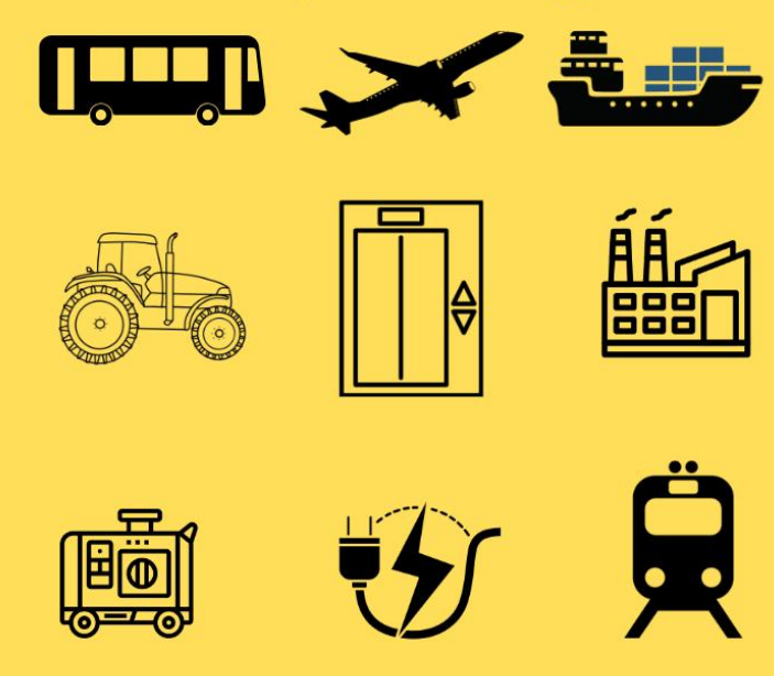
Although the CAN-Bus communication protocol was originally developed for passenger vehicles, it is now used in many different applications.
Applications where the CAN-Bus protocol is used include:
- Passenger vehicles
- Agricultural machinery
- Electric generators
- Industrial automation and machine control
- Elevators
- Railway systems
- Marine vessels
- Robotic applications
- Avionic systems
Today, CAN is commonly used in two main standards: CAN 2.0 and CAN FD.
CAN 2.0 is divided into two groups: CAN 2.0A and CAN 2.0B. In CAN 2.0, the maximum speed is 1 Mbit/s, and both groups allow a maximum of 8 bytes of data to be transmitted per frame.
CAN2.0 A uses the standard format with an 11-bit identifier, while CAN 2.0 B uses the extended format with a 29-bit identifier.
Due to growing demands in the automotive industry, Bosch developed CAN FD (Flexible Data-Rate) in 2011. With CAN FD, higher data rates can be achieved, and up to 64 bytes of data can be sent in a single frame.
While the baud rate in CAN 2.0 is fixed, CAN FD supports a variable baud rate.
CAN-BUS PYHSICAL LAYERS
In CAN communication, a node consists of a microcontroller (MCU) with a CAN controller, connected to a CAN transceiver via CAN TX and CAN RX lines.
Each end of the CAN bus must be terminated with a 120-ohm resistor.

CAN-Bus, which communicates using differential signaling, prevents cross-talk and electromagnetic interference on the communication line.
Thanks to this feature, the CAN-Bus protocol is similar to RS485, Ethernet, and USB protocols.
Since it uses differential signaling, this protocol requires the use of twisted-pair cables.
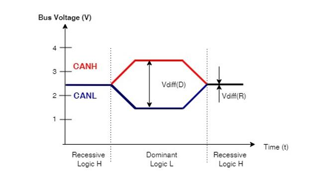
In the CAN communication protocol, there are two different signal levels:
- A recessive bit means there is no voltage difference between CANH and CANL, corresponding to logic 1.
- A dominant bit means there is a 2-volt difference between CANH and CANL, corresponding to logic 0.
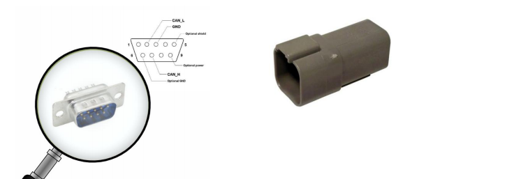
There is no universal standard for CAN-Bus connectors. However, higher-layer protocols often define one or more connector types.
Today, some connector models include a built-in termination resistor.
The most commonly used CAN-Bus connector types include:
- 9-Pin D-Sub
- 6-Pin Deutsch connector (Deutsch DT04-6P)
In the I2C communication protocol, each node has its own address. However, the message ID feature of CAN bus should not be confused with this concept.
In the CAN communication protocol, all nodes can receive messages sent from any node. Additionally, nodes can be added or removed freely without disrupting the communication.
Today, various higher-layer protocols are required to manage CAN communication effectively. The most commonly used ones include:
- CANopen
- DeviceNet
- J1939
BUS ARBITRATION
In a CAN Bus system, when multiple nodes attempt to transmit data at the same time, bus arbitration determines which node gets priority on the bus.
In arbitration, the message with the lower Message ID has higher priority. A dominant bit with a value of 0 is stronger than a recessive bit.
Each node reads back what it sends on the CAN bus. This is called Bit Monitoring.
If the transmitted bit is different from what is detected, the node recognizes a transmission error and stops sending the message.
- ECU1 Message ID: 0x123
- ECU2 Message ID: 0x354
In the above arbitration example, ECU1 will win since it has the lower ID.
A CAN DBC file is a standardized ASCII file that defines the messages to be sent over the CAN bus.
This file describes the format and purpose of each message, making it easier to work with CAN communication during development or testing.
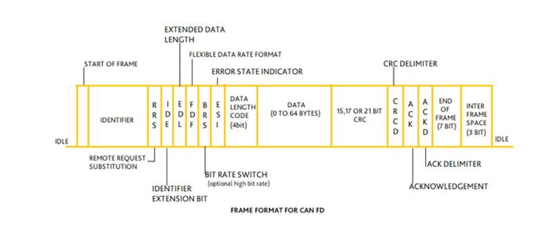
CANBUS COMMUNICATION PROTOCOL – DATA FRAME
- SOF (Start of Frame):
This is the first bit at the beginning of a data transmission. It is a dominant bit. - ID (Identifier):
In the CAN communication protocol, instead of node addresses, message identifiers (IDs) are used.
In Standard CAN 2.0A, the CAN ID in the data frame is 11 bits long, whereas in CAN 2.0B, the ID can be up to 29 bits.- Standard CAN: Uses an 11-bit ID
- Extended CAN: Uses a 29-bit ID
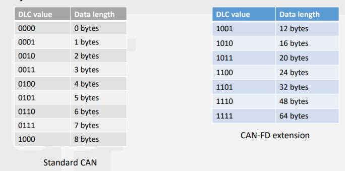
- DLC (Data Length Code):
This 4-bit field indicates the number of data bytes to be transmitted.
For example:- A value of
0000corresponds to 0 bytes - A value of
1000corresponds to 8 bytes
- A value of
- Data:
- Standard CAN supports up to 8 bytes of data per frame
- CAN FD supports up to 64 bytes
- CRC (Cyclic Redundancy Check):
Standard CAN uses a 15-bit CRC for error checking.
In the CAN protocol, the CRC is automatically calculated by the hardware. - ACK (Acknowledgment):
If a message is correctly received by another CAN node, the ACK bit is set to dominant.
If the message is received with errors, the ACK bit remains recessive, and the transmitter will resend the message. - EOF (End of Frame) and IFS (Inter Frame Space):
The 7 EOF bits and 3 IFS bits must be recessive, which indicates to all nodes on the bus that the line is now idle.
After the ACK field and 10 recessive bits, nodes are free to transmit again.

CAN Bus Bit Timing Configuration
In the CAN communication standard, each bit is divided into four segments:
- Synchronization Segment
- Propagation Segment
- Phase Segment 1
- Phase Segment 2
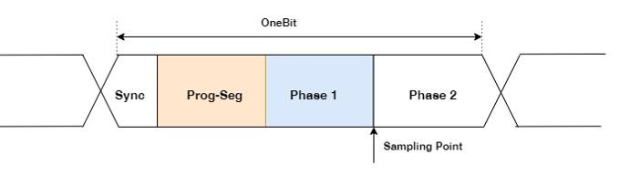
Time quanta is the smallest time unit for one bit in CAN communication.
To calculate the bit rate, you can refer to the following example:
- Baud rate = 500 kbps
- System clock = 40 MHz
- CAN clock divider = 4
- So, CAN clock = 40 MHz / 4 = 10 MHz
time Quanta(tq) = 1/fcan = 1/10 = 100ns
bit rate = 500kbps
bit time = 1/500kbps = 2us
no of tq = 2us/100ns = 20tq
If the sampling point for the CAN message is assumed to be at 80%, then
(Tsync_seg+TSEG1)/(Tsync_seg+TSEG1+TSEG2)=80%
Tsync_seg+TSEG1+TSEG2=20tq
Tsync_seg = 1 (constant value)
(1+TSEG1)/(20)=80%
TSEG1=16-1=15
TSEG2=20-1-15=4
Result:
Tsync_seg=1(fixed)
TSEG1=15
TSEG2=4
Sampling Point = %80
Can prescaler = 4
In microcontrollers, CAN modules can exist in two different forms: MCAN (Modular CAN) and traditional CAN modules.
MCAN is a more advanced version compared to conventional CAN modules.
Traditional CAN Module:
Traditional CAN modules support only the Classical CAN protocol.
- Maximum data length: 8 bytes
- Maximum data transmission speed: 1 Mbps
MCAN Module:
MCAN modules support both Classical CAN and CAN FD (Flexible Data Rate) protocols.
Since CAN FD supports up to 64 bytes of data per frame, it provides a significant advantage in data transmission.
Additionally, CAN FD allows higher speeds, up to 5 Mbps or more.
MCAN also offers a dynamic message configuration structure, making it more flexible.
Due to their optimized architecture, MCAN modules consume less power, making them more suitable for low-power applications.
Features available in CAN FD but not in Classical CAN:
- BRS (Bit Rate Switch):
A feature in the CAN FD protocol that enables two separate bit rates—nominal and fast—for different parts of the frame. This improves transmission speed without compromising compatibility. - ESI (Error State Indicator):
A flag used in CAN FD to indicate the error status of a node.
It shows whether the node is in an Error Active or Error Passive state. - EDL (Extended Data Length):
A flag in CAN FD that determines whether extended data length is used.
When the EDL flag is active, the data length can increase from 8 bytes (in Classical CAN) to up to 64 bytes in CAN FD.
This allows for more flexible and efficient data transmission. - FDF (FD Frame):
A flag that indicates whether a message is in CAN FD format or not. - DLC (Data Length Code):
A 4-bit field that defines how many bytes of data will be transmitted.
In CAN FD, DLC values from 1001 to 1111 represent data lengths of 12, 16, 20, 24, 32, 48, and 64 bytes, respectively.
This extended range is not available in Classical CAN, making CAN FD more suitable for large data transfers.
6-) CRC (Cyclic Redundancy Check):
Due to the higher data rates and increased payload capacity in CAN FD, the CRC mechanism is more advanced compared to Classical CAN.
While Classical CAN uses a 15-bit CRC, CAN FD uses:
- a 17-bit CRC for data payloads of 0–16 bytes, and
- a 21-bit CRC for data payloads of 17–64 bytes.
Leave a Reply